
Use of these procedures on other types of filters such as polypropylene or glass fiber cartridges will not give consistent or accurate results.
Cartridge Installation & Wetting
Prior to any integrity test procedure, the membrane cartridge filter must be sealed in the housing and properly wetted. If the filter is not installed correctly, water or air may bypass the filter membrane and give an incorrect test value.
INSTALLATION
- Cut off the polyethylene bag at the O-ring end of the cartridge. Be careful not to damage the O-rings.
- Remove the polyethylene sleeve from the cartridge. The cartridge must be handled consistent with its intended use. For example, some applications may require special procedures such as wearing gloves, pre-sterilization of the cartridge, etc.
- Place the cartridge into the housing and slowly twist the O-ring end of the filter into the housing until the filter seats.
- Install the housing bell and O-ring or gasket, then tighten the clamp or swing bolt closure to fully seal the housing.
CARTRIDGE WETTING - ith the downstream valves (V8 and V9) and vent valve (V7) open, slowly open the upstream valve (V1) to allow filtered water or the selected test fluid into the housing. Once fluid is observed coming out the vent valve (V7) with no bubbles present in the fluid, close the vent valve and allow the fluid to pass through the housing at 2 liters per minute
- Allow fluid flow for a total of 10 minutes
- Start closing the downstream valve (V9 and V8) to reduce water flow and increase inlet pressure. Bring the inlet pressure up to 15-20 psi by reducing the flow through the downstream valve.
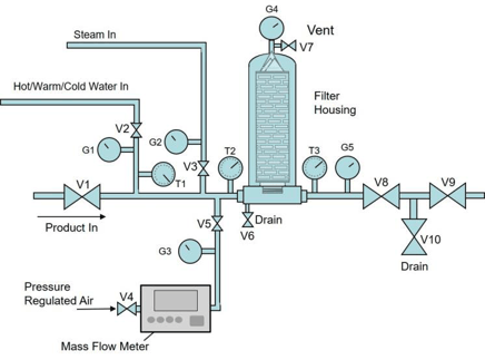
Figure 1: Typical layout for an Integrity Test System
PROCEDURE NOTES
- If the filter application is bacteria removal, then the filter and system should be tested using sterile water and air (filtered to 0.22 microns or smaller) after the filter has been disinfected/sterilized and before use.
If the cartridge requires wetting with a fluid other than the normal process fluid, the user may wet the filter in a separate housing using the procedure described above, then remove the wetted filter and install it in the process system. If the filter application is bacteria removal, then the filter and system should be disinfected or sterilized after the integrity test is complete and before use.
Bubble Point Test Procedure
Refer to Figure 1, which represents a typical layout for an Integrity Test System.
- If appropriate, remove the filter cartridge from the housing used for wetting the cartridge, drain all excess wetting solution from cartridge and install it into the housing used for the integrity testing.
- Starting with all valves in the closed position, open the downstream valves (V8 and V9).
- Connect the pressure regulated air supply line to valve V4. Open the drain valve (V6) and Vent valve (V7) and purge any upstream fluid at 2 psig. Close the drain and vent valves (V6 and V7) when flow becomes mostly air.
- Close valve V9 and open valve V10.
- Increase the air pressure in increments of 2 psig holding for 5 seconds at each step until significantly higher mass flow is measured. Record the pressure when the mass flow increases significantly. This is the bubble point.
- A bubble point value lower than that specified indicates that the system is not integral.
PROCEDURE NOTES:
- Due to the subjectivity in the interpretation of this test, a 10-inch cartridge bubble point is arbitrarily defined as air flow of 50 cc per minute or higher, after the pressure has stabilized.
- If the cartridge appears to fail the initial bubble point test, repeat the Cartridge Wetting procedure and increase the rinse time to twice the initial amount to assure that the media has been properly wetted. Then retest. If necessary, check the cartridge seal in the housing.
Diffusive Flow Test Procedure
Refer to Figure 1, which represents a typical layout for an Integrity Test System.
- Install and rinse cartridges as per Cartridge Wetting instructions.
- Starting with all valves in the closed position, open valves V8 and V9. Downstream must be open to ambient pressure.
- Connect a pressure regulated air (gas) supply and open valve V4. (If possible, pressure should be regulated to the desired test pressure.)
- Open the drain valve (V6) and vent valve (V7) and purge upstream test fluid at 2 psig. Close valves V6 and V7 when flow becomes mostly air.
- Slowly increase the air pressure, as measured on the upstream pressure gauge (G1) or mass flow meter to the amount on the test specification supplied by Critical Process Filtration (usually 80% of the specified bubble point).
- Allow the system to equilibrate. If the regulated air supply is not set at the test pressure, maintain the specified pressure as measured at G4 by adjusting the flow of air using valve V4.
- Record the air flow.
- A diffusional flow (diffusion rate) reading higher than the specification indicates that the system is not integral.
PROCEDURE NOTE: If the cartridge appears to fail the initial diffusion test, repeat the Cartridge Wetting procedure and increase the rinse time to twice the initial amount to assure that the media has been properly wetted. Then retest. If necessary, check the cartridge seal in the housing.
Pressure Decay Test Procedure
Refer to Figure 2, which represents a typical layout for a Pressure Decay Test System.
The Pressure Hold Test, also known as Pressure Decay, is dependent on the specified diffusional flow and volume upstream of the filter and downstream of system valve V1. It can be calculated using the following equation:
Pressure Hold Test Formula:
D (T) (Pa) = (DP) (Vh)
Where:
D = Diffusion rate cc/min
T = Time (minutes)
Pa = Atmospheric Pressure (14.7 psi)
DP = Pressure Drop (psi)
Vh = Upstream volume of apparatus (cc)
- Install and rinse cartridges as per Cartridge Wetting instructions.
- Starting with all valves in the closed position, open valves V8 and V9. Downstream must be open to ambient pressure.
- Connect a pressure regulated air (gas) supply at V4 and open valves V4 and V5.
- Open the drain valve (V6) and vent valve (V7) and purge upstream test fluid at 2 psig. Close valves V6 and V7 when flow becomes mostly air.
- Slowly increase the air pressure, as measured on the upstream pressure gauge (G4) or mass flow meter, to the amount on the test specification supplied by Critical Process Filtration (usually 80% of the bubble point).
- Close valve V5.
- Read the pressure on gauge G4 at the end of the specified test time period.
- The system is considered integral when the measured pressure drop is less than the calculated amount for the cartridge system for the test time.
PROCEDURE NOTE
- If the cartridge appears to fail the initial test, repeat the Cartridge Wetting procedure and increase the rinse time to twice the initial amount to assure that the media has been properly wetted. Then retest. If necessary, check the cartridge seal in the housing.
- Filter Integrity should be tested in accordance with current good manufacturing practice for all critical applications before and after use. It is up to each individual customer to determine the best method and protocol required. The information provided is a recommendation and guide for integrity testing procedures, and the importance of proper cartridge wet out.
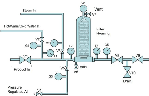
Figure 2: Typical layout for a Pressure Decay Test System